Buying Guides
Power Factor Explained: Why Gensets Are Rated at 0.8 PF

GensetPedia Technical Desk
· 9 min read
The take
Power factor is real power divided by apparent power: PF = kW ÷ kVA. A diesel genset is rated in kVA at 0.8 lagging power factor because it has two limits: the engine limits kW and the alternator limits current, which is kVA. At 0.8 PF both limits are reached together, so a 40 kVA set gives 32 kW. A load below 0.8 lagging hits the alternator's limit first and you get less than full kW. A load at unity PF hits the engine's limit first, so a 40 kVA set still gives only 32 kW. A leading load, from capacitor banks or UPS filters, is the risky case: Cummins advises keeping within the alternator's leading kVAR capability, read from its operating chart.
Power factor is the single number that explains why a genset is sold in kVA and not kW, why a 40 kVA set gives you 32 kW, and why a capacitor bank can upset a generator that runs the same load happily on grid power.
Every diesel genset brochure this site has checked states the rating at 0.8 power factor, lagging. This guide builds it up step by step: what power factor is, how to calculate it, lagging versus leading, why 0.8 is the rating point, and what happens to the alternator on either side of it. Every figure comes from a maker's own published document.
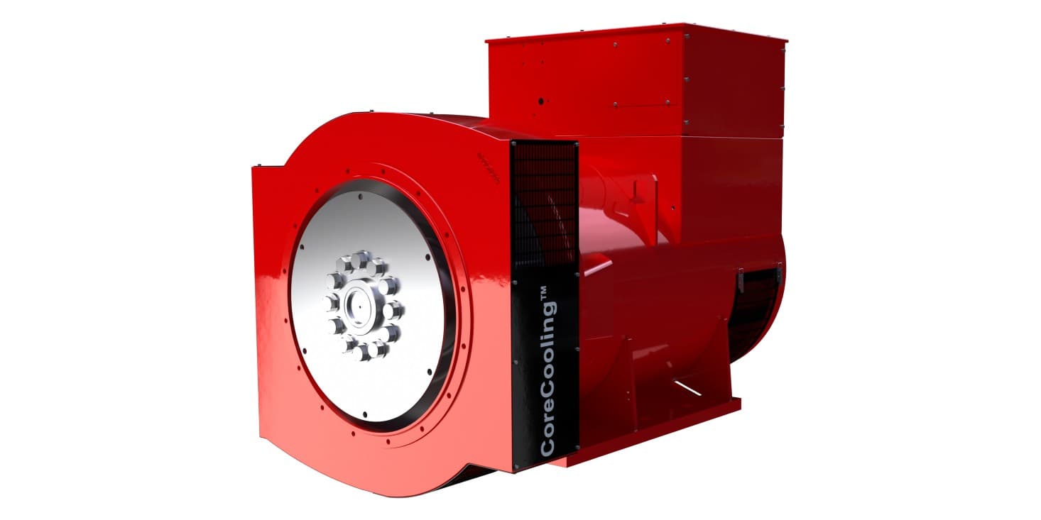
Photo: Stamford S6 alternator (Cummins Generator Technologies), from stamford-avk.com.
What is power factor?
Power factor is the share of the power flowing in a circuit that does useful work.
An AC load draws two kinds of power. Real power, measured in kW, turns a pump, runs a compressor or heats an element. Reactive power, measured in kVAR, is what motors, transformers and fluorescent ballasts need to build and collapse their magnetic fields on every cycle of the 50 Hz supply. Reactive power does no work, but it still flows back and forth through the alternator windings and the cables.
Add the two together (as a right-angled triangle, not by simple addition) and you get apparent power, measured in kVA. That is what the alternator, the breaker and the cable actually have to carry.
Power factor = real power ÷ apparent power = kW ÷ kVA.
A heater has a power factor close to 1: almost everything it draws does work. An induction motor running lightly loaded can sit well below 0.8. A typical mixed site of motors, pumps, air-conditioner compressors and lighting runs at a lagging power factor somewhere in between, which is why the genset industry rates its machines at 0.8.
The power factor formula, with worked examples
Four formulas cover everything a genset buyer needs:
| What you want | Formula | Example (40 kVA genset) |
|---|---|---|
| Power factor | PF = kW ÷ kVA | 32 kW ÷ 40 kVA = 0.8 |
| Real power | kW = kVA × PF | 40 × 0.8 = 32 kW |
| Reactive power | kVAR = √(kVA² − kW²) | √(40² − 32²) = 24 kVAR |
| PF from a meter, 3-phase | PF = kW × 1000 ÷ (√3 × V × I) | 32,000 ÷ (1.732 × 415 × 55.6) = 0.8 |
The triangle matters because it shows the cost of a poor power factor in current. Take the same 32 kW of real power on a 415 V, three-phase supply and change only the power factor:
| Load power factor | kVA drawn for 32 kW | Line current at 415 V |
|---|---|---|
| 1.0 | 32.0 | 44.5 A |
| 0.9 | 35.6 | 49.5 A |
| 0.8 | 40.0 | 55.6 A |
| 0.7 | 45.7 | 63.6 A |
| 0.6 | 53.3 | 74.2 A |
Calculated from I = kW × 1000 ÷ (√3 × 415 × PF).
The work done is identical in every row. The current is not. At 0.6 PF the alternator carries 67% more current than at unity for the same 32 kW, and current is what heats windings. Our kVA to kW guide gives the full conversion chart for standard genset sizes.
Lagging and leading power factor
Power factor has a direction as well as a size.
Lagging means the current waveform peaks after the voltage. Inductive loads do this: motors, transformers, chokes. Almost every traditional genset load is lagging, and the rating "0.8 lagging" assumes it.
Leading means the current peaks before the voltage. Capacitive loads do this: power factor correction capacitor banks, the input filters of UPS systems and the switch-mode power supplies in servers. Cummins' data-centre guidance for specifying engineers lists UPS capacitive filters and IT switch-mode power supplies as leading power factor loads, next to chillers and fan motors as lagging ones.
The difference matters to an alternator. Kohler's engineering paper on complex standby loads puts it plainly: with an inductive load the voltage regulator must increase excitation to hold voltage; with a capacitive load it must reduce excitation. One direction the alternator is built for. The other, beyond a modest amount, it is not.
Why gensets are rated at 0.8 power factor
A genset is two machines on one shaft, and each has its own limit.
- The engine produces mechanical power. It does not care about power factor; it only sees the real power, kW.
- The alternator is limited by heat in its windings. Heat in the stator follows current, and current at a given voltage is set by kVA, whatever share of it is real power.
Rating the set as "kVA at 0.8 PF" states both limits in one line: the alternator can carry the rated kVA, and the engine is sized for 80% of it in kW. The makers print it that way.
Kirloskar Oil Engines, 25–58.5 kVA CPCB IV+ brochure: power factor "lagging, 0.8", ratings "as per ISO8528". Its KG4-40WS1 is 40 kVA and 32 kW. The engine behind it, the 3R1190ETA 4G1, is rated 41.1 kW (56 HP) at the flywheel; the gap to 32 kWe is alternator losses and engine-driven loads such as the radiator fan.
Stamford, the alternator brand of Cummins Generator Technologies, publishes a data sheet titled "Ratings at 0.8 power factor" for its S6L1M-H4 alternator. At 400 V, 50 Hz, Class H continuous rating, it lists 1100 kVA and 880 kW, which is exactly 1100 × 0.8.
Stamford's operating chart for the same machine shows the logic as a picture. Its horizontal "engine" line sits at 0.8 per unit of kW. Its "stator" arc is the 1.0 per unit kVA circle. The two meet at 0.8 power factor lagging. That point, where the engine and the alternator both reach their limit together, is the rating.
This is also why India's genset sizes look odd at first. A 62.5 kVA set is a 50 kW set, an 82.5 kVA set is 66 kW, and a 125 kVA set is 100 kW: round kW figures divided by 0.8.
What happens below 0.8 lagging
When a site's power factor falls below 0.8, the alternator reaches its limit first.
Take a 40 kVA set and a 30 kW load at 0.6 power factor. The kW (30) is under the set's 32 kW, so the engine has spare capacity. But the load draws 30 ÷ 0.6 = 50 kVA, a quarter more than the alternator is rated to carry. The set may run, but the windings run hot, and a protection relay or the alternator itself pays for it.
It is not only the stator. On Stamford's S6L1M-H4 operating chart, the lagging side below 0.8 PF is bounded by a separate rotor limit. To hold voltage against a heavily lagging load, the regulator has to push more field current into the rotor, and the rotor's heating curve sits inside the 1.0 kVA arc. Below 0.8 lagging, the alternator cannot deliver its full rated kVA.
Power factor also changes how deep the voltage dips when a motor starts. Stamford publishes a scaling factor for its locked-rotor voltage dip curves: 0.83 at 0.8 PF lagging, 0.65 at unity and 1.00 at 0.4 PF or below. The lower the power factor of the starting current, the deeper the dip for the same starting kVA. Our guide to block loading capacity covers motor starting in detail.
The fix for a site that runs at low power factor all the time is to size on kVA, not kW, or to correct the power factor at the load. Correction has its own trap on generator power, covered in the leading power factor section below.
What happens at unity power factor
A purely resistive load, such as heaters, a resistive load bank or incandescent lighting, runs at power factor 1.0. Here the engine reaches its limit first.
A 40 kVA genset at unity PF can still deliver only 32 kW. At that point the alternator is carrying just 80% of its rated current, but the engine is at full output. The kVA figure on the canopy is a current limit, not a promise of 40 kW.
Two things improve at unity. Stamford's efficiency curves for the S6L1M-H4 at 400 V show 96.4% full-load efficiency at unity PF, 95.9% at 0.9 and 95.3% at 0.8: less current means lower copper losses. And as noted above, voltage dip on a load step scales down.
One thing can be worse. Cummins' data-centre guidance notes that transient performance is usually documented at 0.8 PF while acceptance tests are usually run on resistive load banks at 1.0 PF, and that resistive loads often give worse voltage transients than inductive ones, because the full kW lands on the engine at once with no inductive lag. If a site's acceptance test calls for a 100% load step on a resistive bank, ask the maker for its transient figures at 1.0 PF, not 0.8.
Leading power factor: the real danger zone
A lagging power factor below 0.8 costs capacity. A leading power factor can cost control.
When a capacitive load is connected, the alternator moves toward over-excitation. Kohler's paper on transferring complex loads describes the response: the voltage can rise when the load is applied while the engine speed dips, and the regulator, already fighting over-excitation, can be slow to let the engine recover. It adds that any leading power factor load "should consider the reactive capability curve of the alternator to avoid regions of instability and/or potential alternator damage."
The alternator's capacity to absorb leading kVAR is much smaller than its rated kVA. On Stamford's S6L1M-H4 chart, the leading side is bounded by "stability" and "excitation" limits that pull in to about half a per unit of leading kVAR at low kW, as read from the chart.
Cummins' worked example in its data-centre guidance makes the same point with numbers:
| Cummins example | Alternator A | Alternator B |
|---|---|---|
| Genset rating | 3000 kW (3750 kVA at 0.8 PF lagging) | 3000 kW (3750 kVA at 0.8 PF lagging) |
| Alternator rating | 4142 kVA | 4464 kVA |
| Leading kVAR capability, alternator basis | ~0.3 pu = 1242 kVAR | ~0.35 pu = 1562 kVAR |
| Leading kVAR capability, genset basis | 0.33 pu | 0.41 pu |
A larger alternator, with lower synchronous reactance, buys more leading capability. Cummins' takeaways for specifying engineers:
- the key parameter is leading kVAR, not power factor; set reverse-VAR protection to match;
- low kW with high leading kVAR is a risk: avoid operating there, disconnect power factor correction or filter capacitors, and select the UPS's "generator mode" if it has one;
- for loads at low leading or lagging power factor, ask for the alternator's capability curve.
The classic Indian case is an APFC panel left in circuit after the changeover. On grid power it corrects a lagging site to near unity. On genset power, at light load, the same capacitors can leave the alternator with more leading kVAR than it can absorb. Our upcoming guide to APFC panels and DG sets covers that in full; for data centres, see genset redundancy for data centres.
How to use this when you size or run a genset
- Find your site's power factor. Many controllers show it: Kirloskar's 25–58.5 kVA brochure lists kVA, kW, kWh, kVAr and power factor on the genset controller. On grid power, a power analyser gives kW and kVA.
- Size on kVA when PF is below 0.8. Divide the kW by your measured power factor, not by 0.8. The GensetPedia load calculator assumes 0.8, so for a site that measures lower, do this one division yourself and size on the larger kVA.
- Do not expect more kW at unity. A resistive load still stops at kVA × 0.8.
- Switch capacitors out on genset power unless the maker has checked them against the alternator's capability curve.
- Ask for the operating chart for any site with large UPS, server or capacitor loads. Stamford publishes one on every alternator data sheet.
To compare real ratings, see the Kirloskar 25 kVA and Cummins 40 kVA data, or the large sets on the Caterpillar 1010–1100 kVA and Mahindra Powerol 1010–1250 kVA pages, and compare models side by side. When two sets run in parallel, our guide to kW and kVAR sharing in synchronization explains how the governors share kW and the voltage regulators share kVAR, and why efficiency changes with load explains the fuel side of running a set lightly loaded.
Figures are quoted as published in Kirloskar Oil Engines' 25–58.5 kVA CPCB IV+ DG set brochure, Stamford's S6L1M-H4 Wdg.312 technical data sheet (Rev. C, 30 September 2025), Cummins' "Specifying Standby Generator Set Requirements for Data Centers" (2022) and Kohler's Power Systems Topics 121, "Transferring Complex Loads on Standby Generator Systems" (2020). Values read from charts are approximate; current and kVA tables are calculated from the formulas shown. Always confirm the alternator's capability with the manufacturer for your load.
Why it matters
Most sizing errors with gensets are power factor errors in disguise. A buyer reads 40 kVA as 40 kW, or connects a motor-heavy load at 0.6 PF, or leaves a capacitor bank switched in on generator power. Each one either overheats the alternator, trips the set or wastes capacity that was paid for.
Specs for the sizes in this article
Frequently asked questions
What is power factor?+
Power factor is the ratio of real power to apparent power: PF = kW ÷ kVA. Real power (kW) is what does the work, such as turning a pump or heating an element. Apparent power (kVA) is what the alternator and cables actually carry. A load at 0.8 power factor uses 80% of the current it draws for useful work; the rest is reactive power (kVAR) that motors and transformers need for their magnetic fields.
What is the power factor formula?+
PF = kW ÷ kVA. For a three-phase supply, PF = kW × 1000 ÷ (√3 × V × I), with V the line voltage and I the line current. The three powers form a right-angled triangle: kVA² = kW² + kVAR². A 40 kVA genset at 0.8 PF delivers 32 kW and 24 kVAR, because 32² + 24² = 40².
Why are generators rated at 0.8 power factor?+
A genset has two separate limits. The engine can only make so much real power (kW); the alternator can only carry so much current before its windings overheat, and current is set by kVA. Rating the set in kVA at 0.8 lagging fixes both: the alternator is good for the kVA and the engine for 80% of it in kW. Kirloskar's 25–58.5 kVA brochure, for example, rates the KG4-40WS1 at 40 kVA and 32 kW with power factor 0.8 lagging, as per ISO 8528.
Can a 40 kVA genset give 40 kW at unity power factor?+
No. At unity power factor the alternator is only 80% loaded at 32 kW, but the engine is at its limit. The genset is sized for 32 kWe; pushing 40 kW would overload the engine. The kVA rating is a current limit, not a promise of that many kW.
What happens if the load power factor is below 0.8?+
The alternator reaches its current limit before the engine reaches its kW limit. A 30 kW load at 0.6 PF draws 50 kVA, which is more than a 40 kVA set can carry, even though 30 kW is under the set's 32 kW. On Stamford's published operating chart, the rotor heating limit pulls the alternator's capability inside its rated kVA on the lagging side below 0.8 PF.
Is leading power factor bad for a generator?+
It can be. Capacitive loads such as power factor correction banks, UPS input filters and switch-mode power supplies push the alternator toward a leading power factor. Kohler notes that a dominant capacitive load can make the voltage rise when it is switched on, while the regulator is already fighting over-excitation. Cummins advises judging leading loads by leading kVAR, not by power factor, keeping clear of operation at low kW with high leading kVAR, and disconnecting power factor correction or filter capacitors on generator power.
How do I find my site's power factor?+
Read it off a meter. Many genset controllers display it: Kirloskar's 25–58.5 kVA brochure lists kVA, kW, kWh, kVAr and power factor on its controller. On grid supply, a power analyser or the maximum-demand meter gives kW and kVA, and PF = kW ÷ kVA.
Found this useful?
Follow GensetPedia on LinkedIn for more genset buying guides and industry data.
Get the weekly digest
New buying guides and market data, once a week — no spam.